Model: Quantifoil R2/2 / Support film - Material: CARBON / Support film - topology: HOLEY
Vitrification
Cryogen name: ETHANE
High pressure freezing
Instrument: OTHER Details: The value given for _em_high_pressure_freezing.instrument is BAL-TEC HPM010. This is not in a list of allowed values {'EMS-002 RAPID IMMERSION FREEZER', 'OTHER', 'LEICA EM PACT2', 'LEICA EM ...Details: The value given for _em_high_pressure_freezing.instrument is BAL-TEC HPM010. This is not in a list of allowed values {'EMS-002 RAPID IMMERSION FREEZER', 'OTHER', 'LEICA EM PACT2', 'LEICA EM PACT', 'LEICA EM HPM100', 'BAL-TEC HPM 010'} so OTHER is written into the XML file.
Sectioning
Focused ion beam - Instrument: OTHER / Focused ion beam - Ion: OTHER / Focused ion beam - Voltage: 30 / Focused ion beam - Current: 0.5 / Focused ion beam - Duration: 10 / Focused ion beam - Temperature: 100 K / Focused ion beam - Initial thickness: 3000 / Focused ion beam - Final thickness: 900 Focused ion beam - Details: Cryo-lift-out lamellae were generated using a second-generation Aquilos (Aquilos II) instrument (Thermo Fisher Scientific). The instrument was operated using the xT user ...Focused ion beam - Details: Cryo-lift-out lamellae were generated using a second-generation Aquilos (Aquilos II) instrument (Thermo Fisher Scientific). The instrument was operated using the xT user interface and the MAPS 3.14 software (TFS). The FIB was operated at 30 kV, and the milling progress was monitored using the SEM beam at 25 pA and 5 kV. A 45deg pretilt shuttle was used for all cryo-FIB milling steps described below. Prior to sample loading, a 100/400 rectangular mesh grid (#G1040-Cu; Science Services) was clipped into an AutoGrid as receiver grid. For clipping, the long side of the rectangle mesh was placed perpendicular to the milling window to allow for easy lift-out attachment and low-angle sample thinning. After loading the sample and receiver grid, overview maps of the high-pressure frozen specimens were acquired and correlated with the images acquired on a Leica EM Cryo CLEM microscope to identify regions of interest. The milling slot on the FIBSEM AutoGrid was used to improve correlation by using its rim, visible in both reflected light microscopy and SEM, as a landmark. The specimen was cleaned from contaminations such as debris and ice in eucentric position at 20deg stage tilt with the FIB operated at 1 nA. Directing the beam to areas with contamination facilitates its removal to create a smooth, clean surface for subsequent coatings. The specimen was sputter-coated with platinum for 30 s at 30 mA and 10 Pa with the built-in sputter coater, followed by a GIS deposition of 1.5 to 2 um metalorganic platinum and another sputter-coating (30s, 30mA, 10 Pa). Tile-scan overview images were taken after each step using the MAPS software. Lift-out sites were identified by CLEM and set to eucentric position. Steps performed for the lift-out FIB milling are explained in greater detailed in Zens et al (2024): Trenches for the lift-out procedure were cut at a stage tilt of 7deg and a relative stage rotation of 180deg to position the FIB perpendicular to the sample. The trenches in front, behind, and to the side of the lift-out were milled in cross-section (CS) patterns with 5 nA. The front and back of the lift-out were polished smooth by milling with cross-section-cleaning (CSC) patterns fitted to the width of the lift-out with 1 nA. Undercuts were performed at 28deg stage tilt, at the default stage rotation, with 1 nA with rectangle milling patterns. The micromanipulator needle was then attached by redeposition milling, using a CS pattern with a Multi-Pass setting of 1 at 0.5 nA. The remaining anchor to the bulk sample was removed at 0.5 nA with a rectangle pattern placed at the anchor position. The lift-out was then lifted out of the bulk sample and transferred to the receiver grid. The grid bars at the attachment site were pre-milled at default stage rotation, 22deg stage tilt, with a CS pattern and a current of 15 nA. The patterns were set up to produce an angled recess matching the width of the lift-out and a z-depth of ~15um. This ensured a better attachment of the lift-out as well as a pre-tilt close to the desired final milling angle. The lift-out was then attached to this recess at eucentric height at a relative stage rotation of 180deg and a stage tilt of 22deg. The lift-out block was maneuvered into the pre-milled slot before attachment by redeposition milling, using CS patterns at 0.5 nA with a Multi-Pass setting of 1, a z-depth of 3 um, and an area of roughly2/1.5 um (x/y). Following visual confirmation of the attachment, the needle was pulled off gently to the side, so it could be directly reused for the next lift-out without any necessary cleaning steps. Each lift-out was then thinned with rectangle patterns to in several steps, reducing lamella width and milling current in each step, resulting in a symmetric stair-like anchor. Final lamella width was approximately 20 um. Lamellae were thinned down to 3 um thickness with 1 nA, then to 1.5 um thickness with 0.5 nA, and to 900 nm using 0.1 nA. Here, the stage was tilted to plus/minus 1deg and the lamella overhangs above and below were milled with 0.1 nA to facilitate a parallel shape of the lamella rather than a wedge-like one. The lamellae were then milled down to 600-900 nm with 50 pA.. The value given for _em_focused_ion_beam.instrument is Aquilos II. This is not in a list of allowed values {'DB235', 'OTHER'} so OTHER is written into the XML file.
-
Electron microscopy
Microscope
TFS TALOS
Image recording
Film or detector model: OTHER / Digitization - Dimensions - Width: 4096 pixel / Digitization - Dimensions - Height: 4096 pixel / Average exposure time: 50.0 sec. / Average electron dose: 4.0 e/Å2
Electron beam
Acceleration voltage: 200 kV / Electron source: FIELD EMISSION GUN
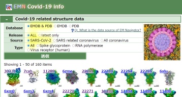
In the structure databanks used in Yorodumi, some data are registered as the other names, "COVID-19 virus" and "2019-nCoV". Here are the details of the virus and the list of structure data.
Jan 31, 2019. EMDB accession codes are about to change! (news from PDBe EMDB page)
EMDB accession codes are about to change! (news from PDBe EMDB page)
The allocation of 4 digits for EMDB accession codes will soon come to an end. Whilst these codes will remain in use, new EMDB accession codes will include an additional digit and will expand incrementally as the available range of codes is exhausted. The current 4-digit format prefixed with “EMD-” (i.e. EMD-XXXX) will advance to a 5-digit format (i.e. EMD-XXXXX), and so on. It is currently estimated that the 4-digit codes will be depleted around Spring 2019, at which point the 5-digit format will come into force.
The EM Navigator/Yorodumi systems omit the EMD- prefix.
Related info.:Q: What is EMD? / ID/Accession-code notation in Yorodumi/EM Navigator
Yorodumi is a browser for structure data from EMDB, PDB, SASBDB, etc.
This page is also the successor to EM Navigator detail page, and also detail information page/front-end page for Omokage search.
The word "yorodu" (or yorozu) is an old Japanese word meaning "ten thousand". "mi" (miru) is to see.
Related info.:EMDB / PDB / SASBDB / Comparison of 3 databanks / Yorodumi Search / Aug 31, 2016. New EM Navigator & Yorodumi / Yorodumi Papers / Jmol/JSmol / Function and homology information / Changes in new EM Navigator and Yorodumi
 Movie
Movie Controller

 Yorodumi
 Open data
 Basic information
 Map data
 Sample
 Keywords
 Homo sapiens (human)
 Authors
 Israel, European Union,
  United States, 4 items
  Citation
 Structure visualization
 Downloads & links
 EMDB map data format
 emd_55811.png
 http://ftp.pdbj.org/pub/emdb/structures/EMD-55811

 Z (Sec.)
 Y (Row.)
 X (Col.)


 Sample components
 Processing
 Electron microscopy
 FIELD EMISSION GUN